Anthropometry Lessons Learned Part II: Challenges Particular to Designing Head and Face Wearables
Designing products for the head and face is particularly challenging for several reasons:
- The spherical shape makes repeatable, consistent alignment challenging
- There are few reliable landmarks on the cranial portion of the head
- Hair obscures the head surface
- Hair types and styles are hugely variable
- All five human senses (sight, sound, taste, smell, and touch) are on the head
As a result, until there is a prototype product to test, we cannot reliably establish where the product will fall with respect to the head surface or the head and face features such as eyes, and ears. In this article we review some of the challenges and suggest how to deal with them.
Lack of Reliable Generic (Not Product Specific) Head Orientation
For most products there is no reliable generic or universal head orientation that is effective for product development. In the technical report Maximizing Anthropometric Accommodation and Protection (Robinette 2007) three orientations were examined for 747 US navy personnel: 1) the Principal Axis System (PrinAx), 2) an approximate corneal plane alignment (Eye) and 3) a top-of-head alignment (TopHead). Figure 1 shows 10 subjects in each of them. The first, PrinAx, provides an orientation that uniformly distributes variability using the principal axes of inertia. The second, the Eye alignment, simulates a pupil location restriction condition that might occur with a helmet mounted display. The third, the TopHead alignment simulates a helmet position restriction that might occur when the helmet comes in contact with the top of the head.
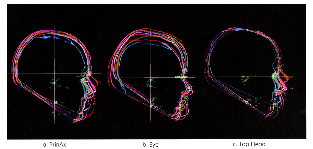
Figure 1. Ten subjects in each of three orientations. (Robinette 2007)
Each of these orientations makes different assumptions about how a helmet would be situated, and the human variability is not minimized with any of them. It is simply moved around. This is further illustrated in figure 2. In this figure we see all the head and face landmark locations for the same 10 subjects in each of the three orientations, from the front view. For PrinAx and Eye orientations the top of the head landmark has huge vertical variability, while for TopHead that variability is zero. For PrinAx and Top Head the pupil variability is huge but for Eye it is very small. The different orientations simply move the variability around based on theories and assumptions about fit location.
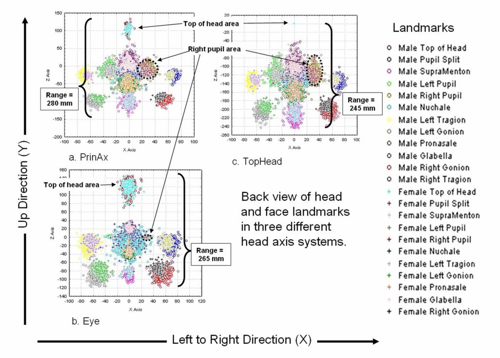
Figure 2. Landmark variability in different head orientations. (Robinette 2007)
Which one is correct? There is no way to know without putting the product on, but probably none of them. They are all just theories until verified with actual product fit.
Head Orientation Impacts Measurements
Some measurements use orientation in the definition, such as Tragion to Top of Head, or Pupil to Back of Head, or even Tragion to Glabella in the fore-aft direction. These measurements are unreliable and inaccurate if the orientation is wrong. The problem is illustrated in figure 3
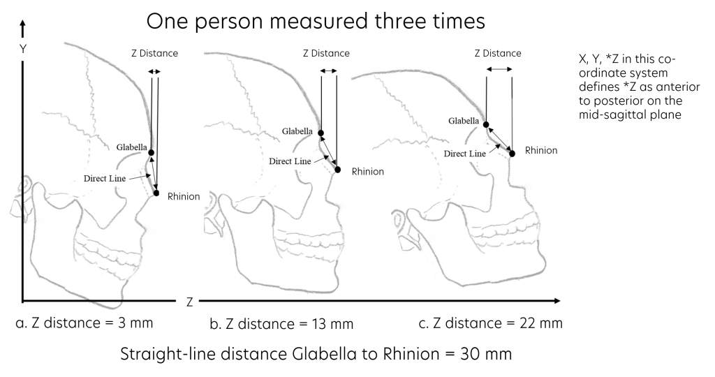
Figure 3. Impact of orientation on z direction measurements. (Robinette et al 2025)
In this figure we see what happens to the Rhinion to Glabella distance in the z direction (fore-aft) when the head orientation changes. The subject doesn’t change, nor does the point to point distance (30 mm), but the z direction measurement fluctuates from 3 to 22 mm, a 19 mm range.
The standard deviations for head and face measurements that are not dependent on the orientation, such as Head Length and Face Breadth are approximately 8 mm for most populations. So, the error in the measurement caused by orientation error for just one subject, is as large as 2.375 population standard deviations for a typical head measurement. When the within-subject error, (like this), is larger than the between-subject error, (or standard deviation), that measurement is meaningless. The variability in the z direction measurement for each subject due to orientation error is larger than the full range of variability in the population’s point to point distance. This means that the z direction measurement is more a measure of orientation error than it is a measurement of a person.
If we are using direction based measurements to place or design a component the only orientation that will yield an accurate and meaningful measurement is one that uses the actual product placed on each subject. This yields the true orientation of the subject with respect to the product.
Product Prototype Orientation Allows for Understanding of Fit
Whitestone and Robinette (1997) illustrated how to create a product based alignment system for helmets. First three landmarks are places on the helmet to define an axis system, such as shown in figure 4. In this example, the three landmarks used to define the axis system were the Helmet Front Landmark, the Helmet Center- Left Landmark, and the Helmet Center-Right Landmark. The helmet was scanned by itself and the landmarks were identified and used to create the axis system. Then each subject was scanned in the landmarked helmet and their right and left pupil locations were identified. Figure 5 shows the pupil locations for a sample of subjects. This shows the true locations of the pupils in the helmet. This can be used to determine design changes needed for helmet mounted displays.
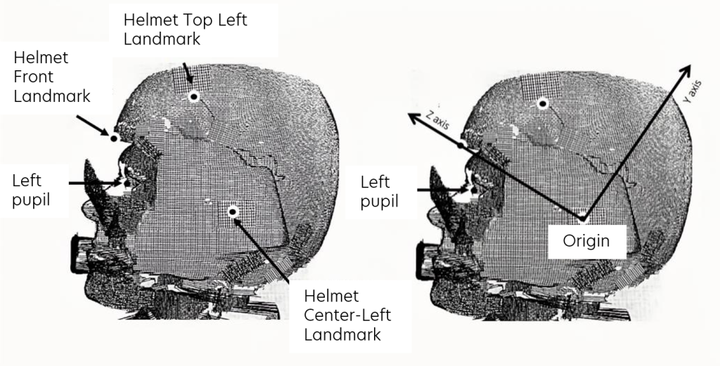
Figure 4. Establishing a product based axis system. (Robinette et al 2025)
Using prototypes of the product in a fit test, and scanning with and without the product can also help us understand product fit. In figure 6 we show two subjects in a top down view of one subject. (Product details are simplified for confidentiality reasons.) These two subjects have nearly the same measurements and comfort scores, but one failed for slippage while the other passed. Looking at the cross sections from the top view we see that subject 59’s Face Breadth was closer to the front of his head than subject 10’s face breath. This caused a gap at the back that made it looser on him. This is something we could only measure and view using 3D scans with and without the prototype product.
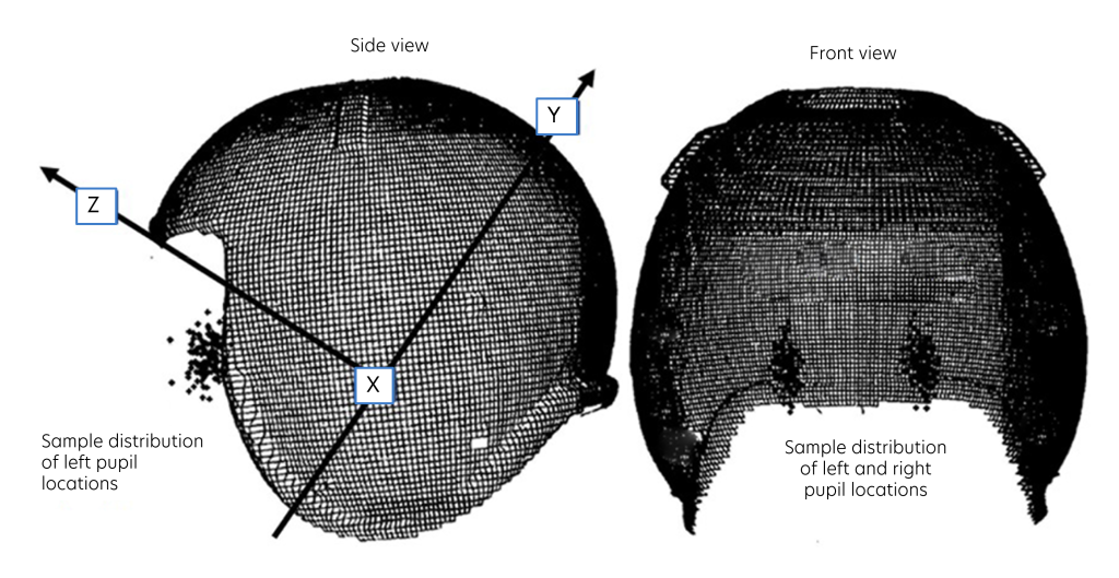
Figure 5. Pupil locations identified by having the subjects wear the product. (Bredenkamp 2025)
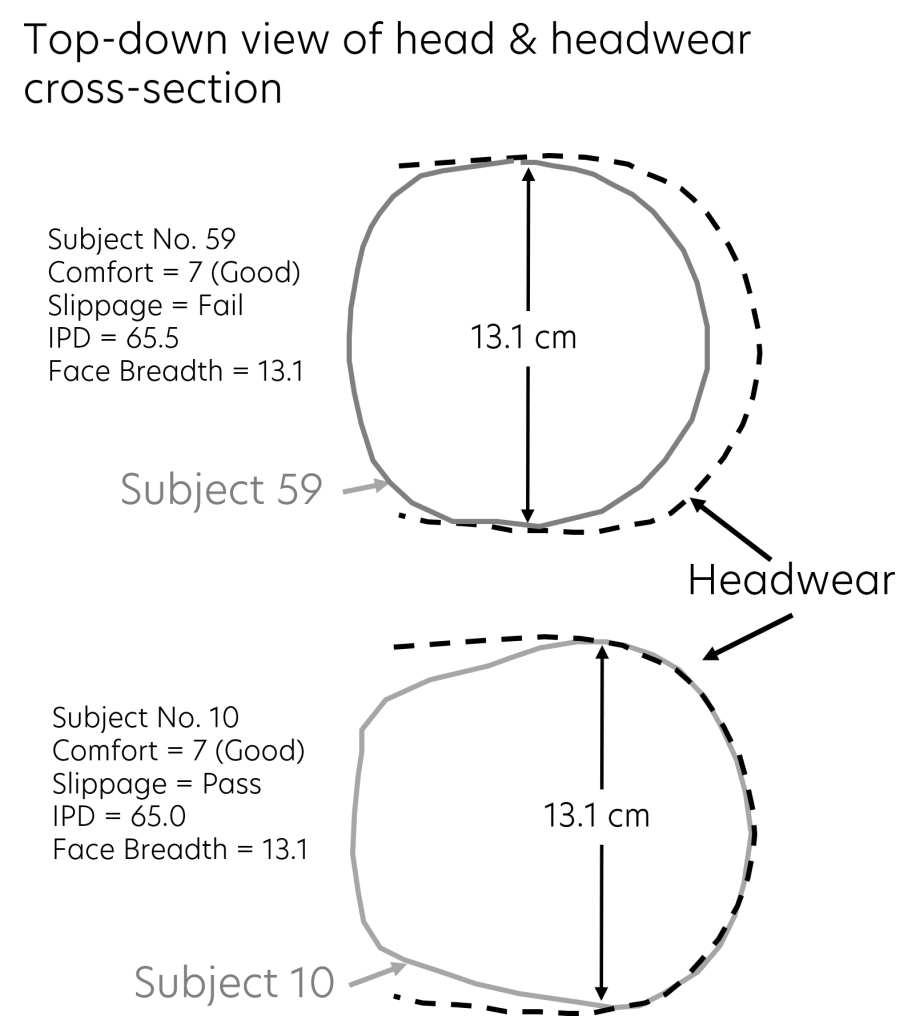
Figure 6. Two subjects in one size of headwear with their fit scores. (Bredenkamp 2025)
There are other ways to measure the interface of the product with the person as well. Figure 7 shows a heat map, or clearance/pressure map of the product with respect to the wearer. This is created by overlaying the scan or CAD file of the product on the scan of the subject and measuring the differences. It doesn’t tell us if the pressure is too much or not enough, but it does tell us where the product is on the person. Fit assessment scores can tell us if it is a good fit in the position or not. We recommend collecting fit scores, pass/fail results, anthropometry and scans in and out of the product.
Figure 7. Clearance/pressure map of product on person. (Bredenkamp 2025)
Summary
Virtual product placement without using a product prototype on a real person is unreliable. Fit assessment combined with 3D scans, with and without the product, provides us with the ability to visualize and understand fit in ways that were not possible before the availability of scanning technology. This is extremely useful during the product development process because it allows us to understand and make changes early in the process when changes are less expensive.
More information on how to use fit testing for head products in the design and development process is available in Robinette, K.M., Veitch, D., Alemany, S., & Bredenkamp, K. (2025). Product Fit and Sizing: Sustainable Product Evaluation, Engineering, and Design (1st ed.). CRC Press. https://www.routledge.com/Product-Fit-and-Sizing-Sustainable-Product-Evaluation-Engineering-and-Design/Robinette-Veitch-Alemany-Bredenkamp/p/book/9781032491189
If you would like someone to help, Anthrotech provides this type of consulting service.
References
Bredenkamp, K. (2025) Head and Face Wearables, in Product Fit and Sizing: Sustainable Product Evaluation, Engineering, and Design, chapter 6, pp. 268-338, CRC Press, ISBN 9781032491189
Robinette, K. M., Veitch, D., Alemany, S., and Bredenkamp, K. (2025) Product Fit and Sizing: Sustainable Product Evaluation, Engineering, and Design, CRC Press, ISBN 9781032491189
Robinette, K.M. (2007) Maximizing Anthropometric Accommodation and Protection, AFRL-RH-WP-TR-2008-0022, August 2007, Air Force Research Laboratory, Human Effectiveness Directorate, Biosciences and Protection Division, Biomechanics Branch, Wright-Patterson AFB OH.
Whitestone, J.J. and Robinette, K.M. (1997) Fitting to maximize performance of HMD systems, in Head Mounted Displays, Designing for the User, editors Melzer, J. and Moffitt, K., chapter 7,pp. 175-206, McGraw Hill Publishing, New York, New York.
Anthropometry Lessons Learned Part I: Mythical Average, 5th and 95th Percentile People
Anthrotech Connections Newsletter – May 2025
Anthrotech is at the forefront of the ever-changing field of anthropometry.
"*" indicates required fields